
With Huawei's core concept for ODN construction centering on full and dense coverage coupled with short and easy access, Huawei's ODN 3.0 solution uses two transformative technologies to support five typical network scenarios.


By Zhao Maiqing, CTO, Home Broadband Solutions, Huawei
Two key transformative technologies in ODN 3.0
In the earliest FTTH solution, ODN 1.0 optical splitting was used for optical splitters, while fusion splicing or mechanical splicing was reserved for fiber connections. In 2015, some vendors implemented drop cable pre-connection by connecting fiber drop cables to fiber access terminals (FATs), forming the ODN 2.0 solution. Since 2018, based on ODN 2.0, Huawei has gradually realized pre-connection between distribution optical cables and level-2 optical splitters, uneven optical splitting of level-2 optical splitter FATs, and pre-connection between fiber feeder cables and level-1 optical splitters. This has resulted in a comprehensive solution that implements full pre-connection, cascading, and uneven optical splitting technologies, culminating in the ODN 3.0 solution.
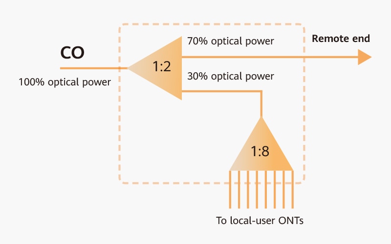
Figure 1: Uneven optical splitter
1. Uneven optical splitters: Efficient connections and reduced costs
An uneven optical splitter (as shown in Figure 1) unevenly splits 100% of optical power signals from COs, with 70% of output allocated to remote ends and 30% retained for local users, and then evenly splits the portion of optical power between local users. Although only 30% of optical power is retained for local users, it is sufficient to meet local users' needs.
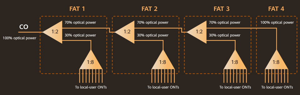
Figure 2: Four-level cascade with uneven optical splitting
Several uneven optical splitters are usually cascaded together. For example, for four-level cascading, as shown in Figure 2, the first three splitters perform uneven optical splitting, and the fourth performs even optical splitting. This means 100% of the optical power from the CO is retained for FAT 4 users. Although the third and fourth splitters receive only a relatively small amount of CO optical power, it is still sufficient to meet the needs of the local users.
Uneven optical splitters are advantageous in that they significantly reduce the number of optical cables required. Only a single-core optical cable is needed between the four optical splitters and between the optical splitters and the CO. By contrast, an even optical splitting solution would require four optical cables, as shown in Figure 3.
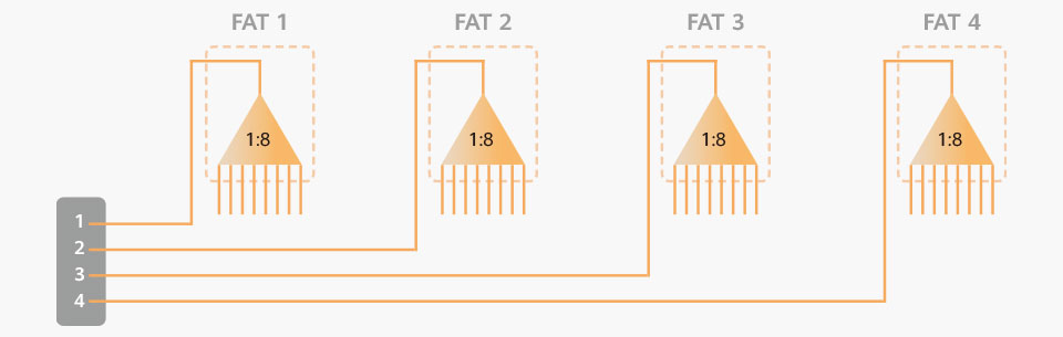
Figure 3: Four-level cascade with even optical splitting
Generally, in an ODN project, costs related to optical splitter material and installation account for less than 15% of total investment, while 85% of investment relates to optical fibers.
Therefore, uneven optical splitting is an advanced and revolutionary development for FTTH network solutions.
2. Pre-connection: Reduced faults for ODNs
An FTTH ODN is a network of optical fibers connected to different devices, such as optical splitters, FATs, and optical cable junction boxes. One way to connect these fibers is using fiber fusion splicers onsite, but fiber splicing requires highly skilled technicians and can be very difficult if operation sites are unfavorable. Another way is mechanical splicing, which is simpler than fiber splicing. However, poor connection quality can result in faults or excessive signal attenuation within just three years. Furthermore, both methods require device cover plates to be removed from boxes, meaning exposure to the weather and compromised protection of components over time. Most ODN faults actually occur at these junctions. A typical example is tail-end optical splitters inside FATs. Frequent removal of FAT cover plates during onsite installation and repairs often leads to faults over time from compromised protection.
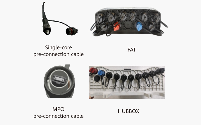
Figure 4: Pre-connection devices
Pre-connection (Figure 4) means fiber sockets are reserved outside an FAT, and a fiber plug is reserved in the factory, so that the plug can easily be fixed to the socket at the construction site. Pre-connection ensures that FATs never need to be uncovered. Of course, reliable pre-connection and adequate optical attenuation requires firm conjunctions, meaning both the sockets on devices like FATs and the pre-connection plugs of optical fibers must strictly be manufactured to a high standard.
OLT options in FTTH networks
An FTTH network (Figure 5) consists of three parts: OLT, ODN, and drop cable segment. Generally, the ODN part is referred to as home pass (HP), and the drop part is referred to as home connection (HC). HP consists of the feeder section and distribution cable section.Several types of OLT can be used depending on the actual scenario (Figure 6).
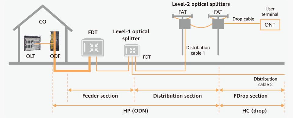
Figure 5: FTTH network
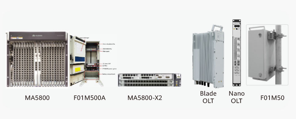
Figure 6: Different types of OLTs
1. Indoor OLT
Applicable to COs or indoor base stations, each OLT can typically carry 4,000 to 6,000 users and each OLT rack can house two or three OLTs. Generally, the coverage radius, that is, the distance between an OLT and the farthest optical network terminal (ONT), should be a maximum of 6 kilometers.
2. Outdoor OLT
When no indoor equipment room is available, an outdoor OLT cabinet is typically installed in an open outdoor space, preferably where base stations are located. A dedicated concrete base will be built in advance for such OLTs to keep water out. Each outdoor cabinet houses only one OLT, typically covering 4,000 to 6,000 users. WDM and IP equipment can also be installed in outdoor cabinets as required. Power supply and storage batteries are required in the cabinets, while natural air cooling, fan-based air cooling, or dedicated air-conditioning can be selected based on local temperatures.
3. Compact OLT
Blade OLT: OLTs of this kind are compact and weigh about 13 kilograms. These OLTs can be installed on a pole or in an open space within a base station. They can carry 1,000 FTTH users each, or 2,000 FTTH users when two units are installed back to back and share two uplink optical fibers to the CO.
MA5800-X2: This OLT model can be installed inside a mini outdoor cabinet which is then fixed at a base station or street cabinet to support up to 2,000 users per unit.
Nano OLT: This type of OLT provides only four GPON ports and can carry 256 broadband users. It is smaller and lighter than other OLTs, and can be installed inside a mini outdoor cabinet which is then fixed outdoors. Nano OLTs are particularly suitable for rural areas, as they are an extraordinarily low-cost solution for areas with small populations and low household density.
Core concepts in ODN design
1. Another look at two carrier KPIs
Port Take-up Rate = Number of Subscribers (in an area) / Number of FAT Ports (in an area)
Traditionally, carrier performance is evaluated according to take-up rate. This is problematic because carriers tend to require high port-take-up rate soon after project acceptance. Setting a high port-take-up rate as a KPI for the first two years after project completion will inevitably result in fewer ports being planned for the initial phase of the project. This will mean sparser coverage and longer access lines, leading to repeated construction that wastes both time and investment. Generally, a 30% take-up rate within three years after an FTTH project is completed is already considered fair performance. For a large-scale, multi-area FTTH network construction project, a total take-up rate of over 50% within five years of project completion would be considered impressive performance. Some carriers require their local business units to achieve a take-up rate of more than 70%. This is incredibly difficult to achieve when they are developing the business at scale.
Household Penetration Rate of Ports = Number of FAT Ports (in an area) / Number of Households (in an area)
Household penetration rate of ports means the number of optical fiber ports to be deployed for every 100 households in an area. Carriers that emphasize lower CAPEX will reduce the number of ports planned for the first phase of construction projects, resulting in low household port penetration rate.
The CAPEX of an FTTH project typically comprises construction labor (60%), optical cable (25%), devices like optical splitters (15%), and minor costs such as design and supervision. Labor cost clearly accounts for the majority of the total cost. A low household penetration rate of ports will mean two, three, or even more phases of construction are required over just one or two years, with each phase resulting in basically the same labor cost. Three more phases of construction mean three times the required investment compared with everything being done at once.
Therefore, a 70% or higher household penetration rate of ports is recommended to be achieved following the very first phase of FTTH construction.
2. Full and dense coverage, short and easy access
-
Full coverage: Key to one-time holistic planning
One-time holistic planning should be performed for small- and medium-sized cities to achieve full coverage in one deployment, without requiring secondary design and construction. The FTTH construction project of a city should have as many areas as possible contiguously and fully covered, again in one deployment. This is especially true for traditional fixed network carriers, because they need to migrate existing xDSL users across all areas to FTTH.
Full coverage is required for user volume to ramp up across an area or city and for carriers to build their brand influence, because existing users will pass on their experience to potential new users through word of mouth.
By contrast, interspersed coverage may result in consumer complaints and negative market effects in non-covered areas. This may encourage competitors to fill coverage vacancies through repeated construction and compete for users.
-
Dense coverage: Improving return on investment and market confidence
Dense coverage means a 60% or higher household penetration rate of ports. This reflects carriers' expectations for and confidence in the market.
Dense coverage can improve ROI, shorten project duration, and ensure high network operations quality, while enhancing confidence in market development, reducing management costs, and reducing competitors' market expectations.
A 60%–100% household penetration rate of ports is recommended, as the number of FAT ports in an FTTH network is a rational standard for measuring a carrier's network capabilities, which represents medium- and long-term market development potential. This is intended to support development over at least the next five years, and carriers should not expect a high take-up rate in the first year of project completion.
-
Short access: Improving FTTH installation efficiency
For areas with average resident density, 8-port FATs are recommended. For areas with low resident density, 4-port or 2-port FATs can be used. The average access distance between an FAT and a household ranges from 30 meters to 80 meters.
Shorter access ensures efficient installation. Broadband installations per capita per day is a major factor affecting the scale of carriers' user development and total HC installation costs. FTTH networks are a key foundation for developing broadband users at scale. High-quality network construction will mean efficient device installation, low fault rate, good user experience, and a good service brand.
-
Easy access: Quick installation and troubleshooting
The end-to-end pre-connected FAT solution eliminates the need for high-altitude fiber splicing while decreasing the failure rate caused by fiber clamping. When a FAT is faulty, it can simply be replaced. This ensures quick installation and troubleshooting for FATs.
3. Drawbacks of sparse coverage and long access
Sparse coverage and long access are the main reasons for poor ROI for global carriers in FTTH deployment over the past decade or so. Repeated construction in the same area is the primary reason why some carriers fail to succeed in FTTH, as this wastes investment, time, and market opportunities.
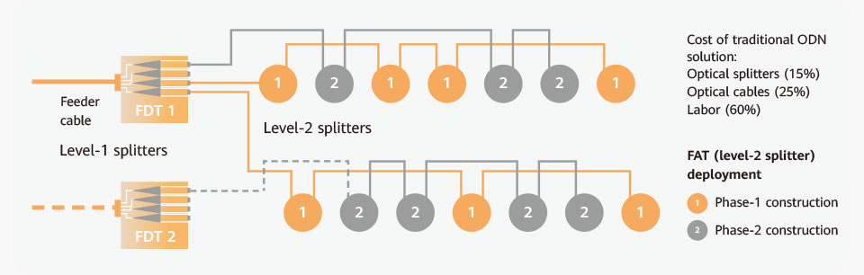
Figure 7: Investment wasted due to secondary construction
-
Sparse coverage means wasted investment for secondary construction
Sparse coverage in the initial phase of construction results in a huge waste of investment for a second phase of construction.
Figure 7 shows a typical case of secondary construction. The total investment required to achieve a 70%–90% household penetration rate of ports over two phases of construction is twice that required to achieve this over a single phase. Some carriers encounter a shortage of available ports and a budget crunch despite constant construction projects in virtually the same area year after year. Typically, this situation is primarily caused by the dogmatic practice of evaluating performance according to take-up rate, resulting in a shortage of upfront investment and subsequent repeated construction. Generally, during the second and third phases of construction, identifying idle fibers in fiber distribution terminals (FDTs) is more time-consuming than laying new optical cables. Some carriers end up having as many as three to five phases of construction in the same areas, wasting huge investment.
-
Long access leads to high installation costs
Figure 8 shows a typical case of long access. Due to a sparse coverage approach, users in the area are covered by only FAT 1, deployed during the first phase of construction. When users 4, 10, and 11 subscribe to the broadband service, their access to an FAT can only be delivered over a long distance.
As FAT 1 ports become almost fully loaded, FAT 2 is installed through second-phase construction to address additional user needs. However, users 4, 10, and 11 who were connected to FAT 1 cannot be migrated to FAT 2.
When FAT 1 is fully loaded and no idle port is available, new users near FAT 1 (e.g., user 7) can only be connected to FAT 2. In this case, the HC installation distance is very long, significantly increasing installation costs.
Deploying the two FATs at the same time can prevent the long-access problem caused by sparse coverage and address the high total installation cost resulting from high labor costs of HC installation. The criteria for evaluating FTTH network construction involves how many broadband lines an engineer can install per day. Therefore, it is recommended that the average distance between an FAT and a household be a maximum of 100 meters.
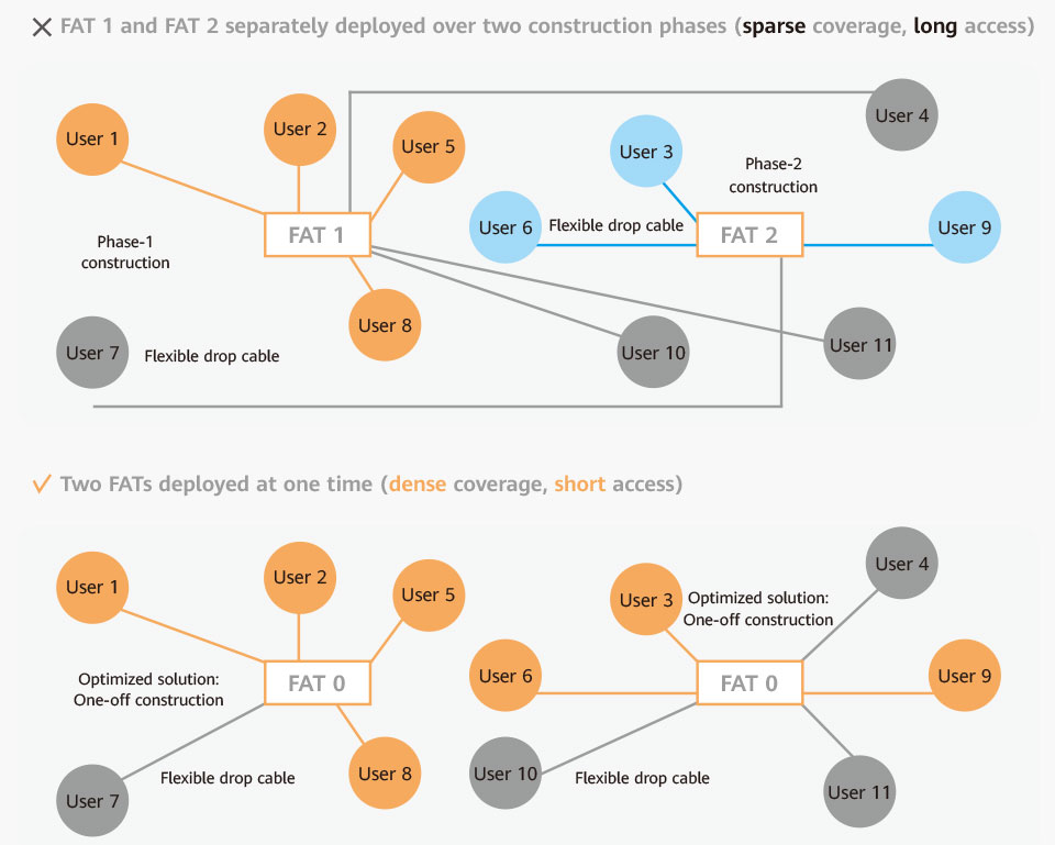
Figure 8: Long access increases the HC installation cost
Three keys to ODN design
1. Locations of level-1 splitters (hub boxes)and level-2 splitters (FATs)
FATs should be located as close to consumers as possible. For example, an 8-port FAT, which can connect to eight households, should be located with the shortest average distance to the eight households it connects to.
The capacity of a hub box should first be identified to determine the maximum number of FATs that can be connected to it. For example, a hub box that can cover eight groups of FATs, with four FATs in each group, should be located with the shortest average distance to the eight groups of FATs it connects to.
Of course, the exact locations of FATs and hub boxes are the result of a comprehensive analysis of onsite conditions.
This is the only way to ensure the minimum number of optical cables used between hub boxes and a CO, as well as the shortest distances between hub boxes and FATs and between FATs and consumer homes. Ensuring this minimizes the optical cable investment required in the feeder section, distribution cable section, and HC section.
Neither putting level-1 splitters inside COs nor installing multiple level-2 splitters in a street cabinet is advisable, as both approaches would result in unsuitably long distances between the FATs and consumers' homes — far more than 100 meters. Laying a large number of drop cables inside street cabinets and underground pipes requires enormous investment and makes future maintenance more difficult.
The feeder cables between COs and level-1 splitters are considered scarce resources, so using the minimal number is recommended.
Given the fixed number of optical cables between level-1 and level-2 splitters and between level-2 splitters and ONTs, their lengths should be minimized.
2. Leveraging existing network resources
COs, wireless base stations, and existing FDTs already have the power supply and optical cable resources required for FTTH networks, such as outgoing optical cables from COs and redundant optical cables between base stations or optical nodes and COs. Deploying OLTs where these existing resources can be leveraged will help reduce the need to deploy new optical cables in the feeder section, which is typically long and comes with a large number of fiber cores, and will help reduce additional investment in deploying the power supply.
3. Replacing traditional ODNs with ODN 3.0
The technical design and construction of ODN 3.0 are simple and efficient, and the ODNs can run stably with low fault rates, reducing ODN maintenance costs. If the fault rate of carrier ODNs that are built earlier is too high to keep maintenance costs down, then carriers can consider replacing legacy ODNs through maintenance investment.
Overview of the ODN 3.0 solution
1. Solution for high-density, low-rise, overhead scenarios
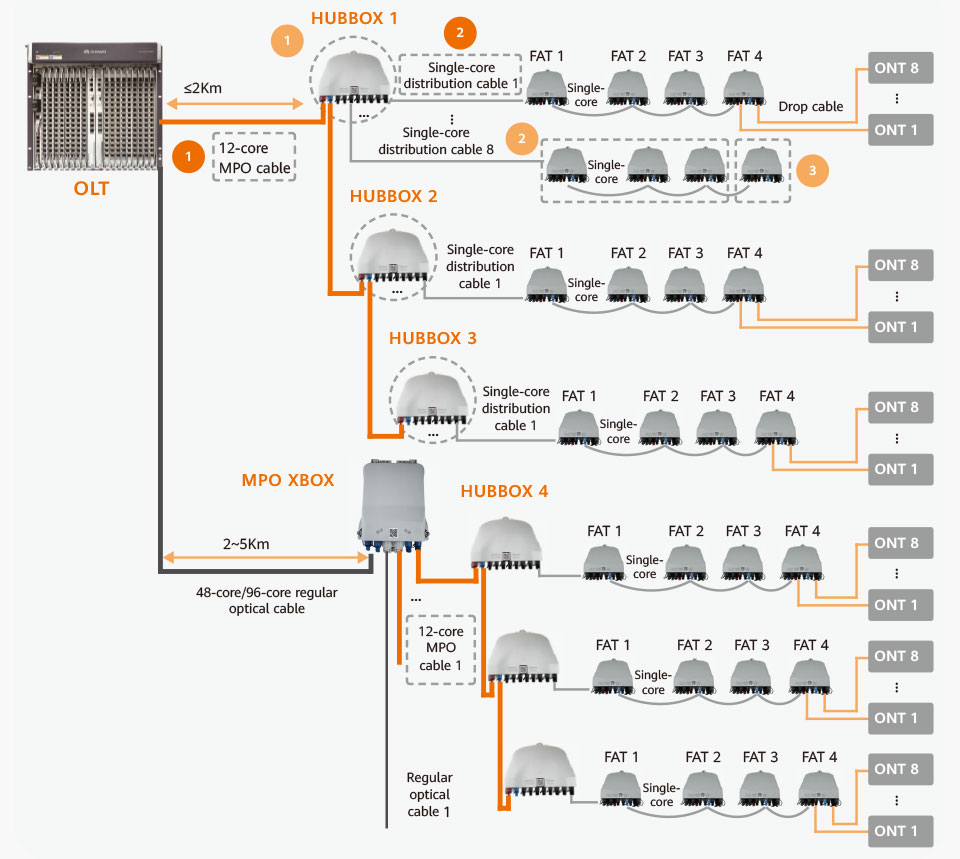
Figure 9: Solution for overhead deployment in high-density, low-rise facilities
As shown in Figure 9, this solution consists of three types of boxes (hub boxes, sub-boxes, and end boxes) and three types of optical cables (MPO cables, single-core distribution cables, and drop cables). Each hub box performs 1:2 optical splitting on the fiber cores of the four GPON ports and outputs eight links. Sub-boxes use uneven optical splitting and can consist of four cascaded FATs, with each connected to eight households. For areas that are far away from an OLT, a regular optical cable and an MPO X-box can be used. X-boxes can be directly connected to both 12-core pre-connected optical cables and regular optical cables for output. This solution uses end-to-end pre-connection, and is suitable for overhead-deployment scenarios, with high installation efficiency and low fault rates.
2. Solution for overhead deployment in low-density areas
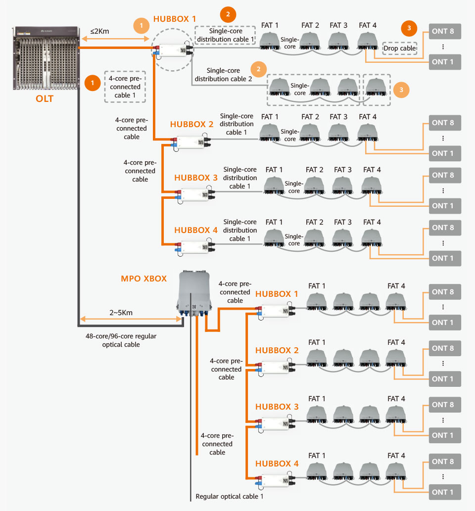
Figure 10: Solution for overhead deployment in low-density areas
In this solution, as shown in Figure 10, each hub box has a 1:2 optical splitter built in. FAT 1–FAT 3 use uneven optical splitting with eight ports, while FAT 4 uses even optical splitting. The three types of optical cables involved are 4-core pre-connected cables, single-core distribution cables, and single-core pre-connected drop cables. If the covered area is close to the CO, a 4-core pre-connected cable can connect the four GPON ports of the OLT with four hub boxes, thus supporting up to 256 households in total.
3. Solution for multistory buildings
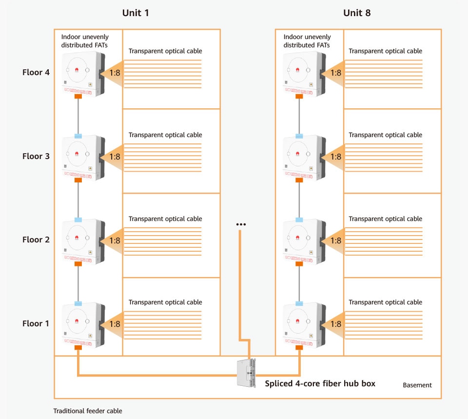
Figure 11: Solution for multistory buildings
This solution, as shown in Figure 11, uses a traditional feeder cable connected to a hub box in the building. Each hub box has four built-in 1:2 optical splitters to output eight links, each with with four cascaded FATs, covering up to 32 households in a building unit. With eight building units covered, where each unit has four stories and each story has eight households, up to 256 households can be supported in total.
4. Solution for underground deployment
In this scenario, it is recommended that level-1 optical splitters (hub boxes) are installed in street cabinets. If possible, the coverage area of level-1 splitters should be narrowed so that hub boxes are as close to the covered FATs as possible to shorten the distance between them.
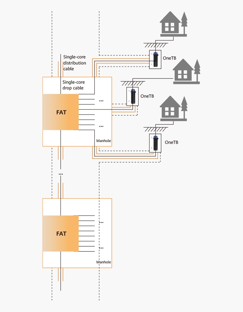
Figure 12: Solution for underground deployment
The FATs shown in Figure 12 are level-2 splitters. It is recommended that these FATs are installed on walls inside manholes. 8-port or 4-port FATs can be used depending on the household density in the area. Pre-connection is used between FATs and households, and OneTB's (underground) are deployed outside household doorways. Pre-connected cables used between FATs and OneTB's can be vertically deployed in the same trenches as distribution cables. In addition, protection pipes that lead all the way to household doorways can be added for these cables, where a trench is dug horizontally, and the cables are connected to OneTB's.
Optical cables between hub boxes and FATs and between different FATs can be pulled through conduits or blown through microducts. The greatest benefit of this solution is that it does not require secondary ground excavation at household doorways. Of course, it also has other significant benefits, such as shortened HC length and distribution optical cable length, as mentioned previously.
5. Leveraging existing backbone cable resources
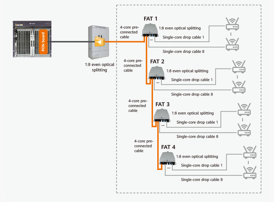
Figure 13: Reusing existing FDTs to expand the network
One solution is to reuse existing FDTs to expand the network (Figure 13).
The benefit of this solution is that it allows the utilization of existing feeder optical cables and FDTs, with pre-connection used on sections beyond the FDT, removing the need for fiber splicing. Fiber splicing needs to be performed only once at the FDT to connect the traditional optical cable with the 4-core pre-connected optical cable that is connected to FATs. Each FAT performs 1:8 splitting on an optical fiber to connect to eight households.
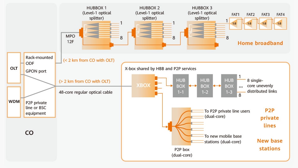
Figure 14: Reusing existing backbone optical cables
Another solution is to reuse existing backbone optical cables to develop B2B services and fiber to the site services (Figure 14).
The biggest problem with traditional ODNs is low optical cable utilization due to multi-core cables laid over long distances. Along the routes from the CO to optical splitters, there are multiple optical cable splicing points such as FDTs and optical closures. These cause high fault rates and optical attenuation, difficulties with maintenance and troubleshooting, and complex resource management.
The P2P box used in the ODN 3.0 solution can directly output dual-core optical cables to P2P private line users and mobile base stations. Therefore, this solution is particularly suited to supporting integrated carriers with deploying networks and fully leveraging their backbone optical cable resources.